Conmutador WiFi para electrodomésticos con ESP8266
Aprende a construir tu propio switch WiFi con el módulo ESP y cómo controlar cualquier electrodoméstico de tu lugar favorito.

¿Qué son los conmutadores WiFi?
Hoy en día vivimos en la era del Internet de las Cosas, y los interruptores wifi son la base de esta. Son dispositivos que pueden encender, apagar o atenuar electrodomésticos como luces, ventiladores, etc., de forma remota o autónoma, controlados por nuestros teléfonos móviles, nuestra voz, la temperatura ambiente o incluso el pronóstico del tiempo.
¿Cómo funcionan?
Se basan en la comunicación inalámbrica (comúnmente conocida como WiFi) que les permite conectarse a internet y procesar datos, para poder actuar ante determinadas condiciones establecidas por el usuario.
Requisitos de aplicación:
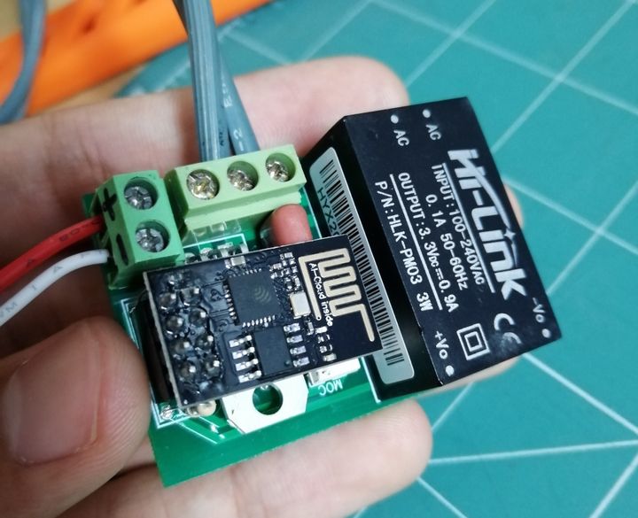
- Módulo ESP8266 (ESP-01)
- placa PCB
- Tablero de circuitos
- Cables de cableado
- Cuenta Ubidots
- Arduino nano
1. Esquema:
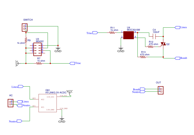
Materiales:
3 resistencias de 1k ohmios y 1/4w
2 resistencias de 470 ohmios y 1/2 W
1x conector hembra dual en línea (U3)
1 condensador de 100 nf y 400 V
1 fuente de alimentación Hi-Link de 3,3 V
PCB: ¡Enlace para descargar archivo Gerber!
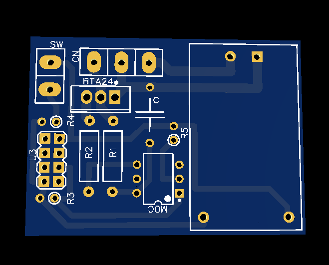
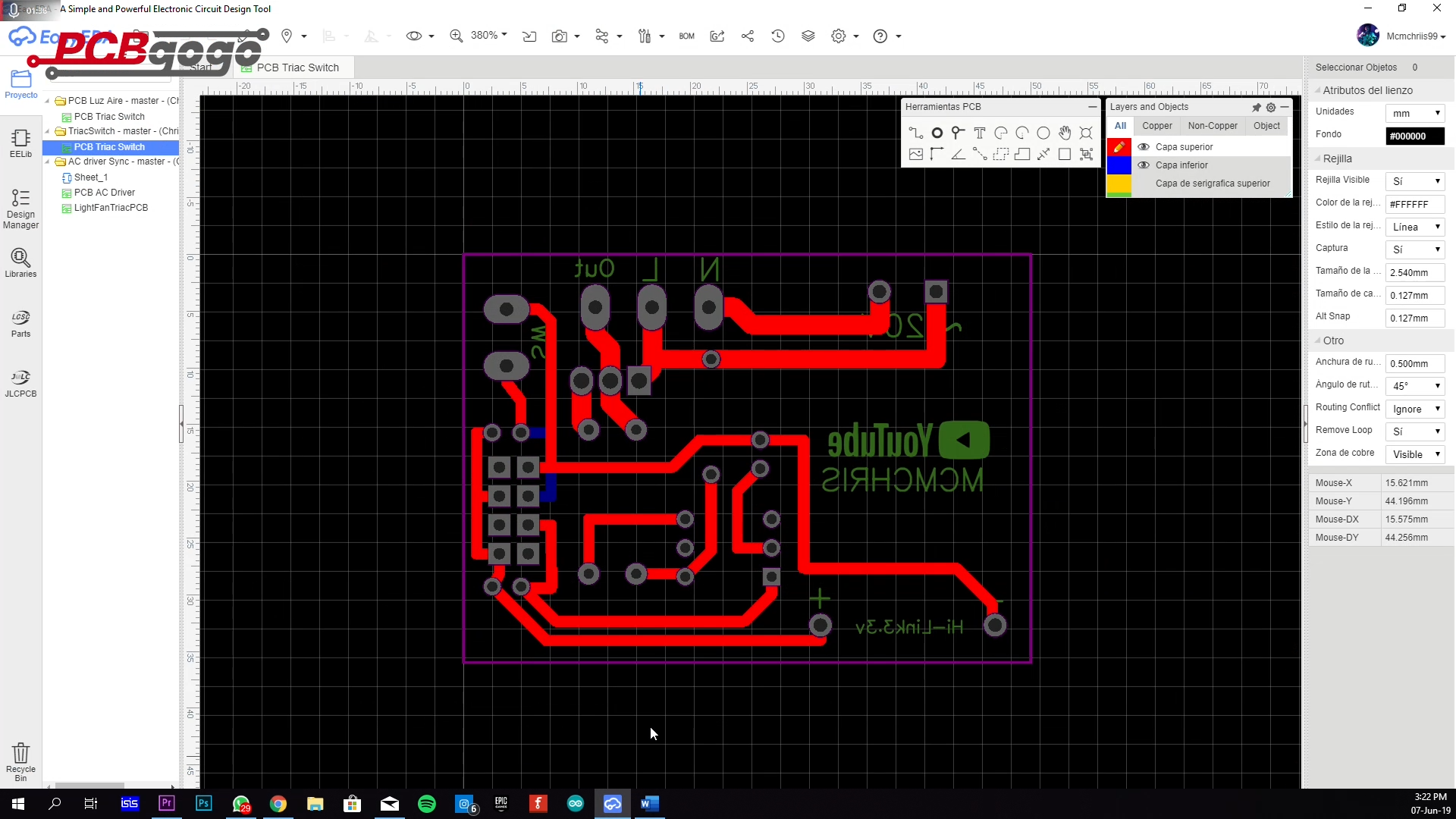
PCB fabricado con PCBGOGO (Industria de fabricación de PCB)
2. Ubidots Creación de dispositivos y variables.
Vaya a la sección Dispositivo de su Ubidots y cree un nuevo dispositivo llamado " wifiswitch ".
Dentro de su dispositivo " wifiswitch ", cree una variable llamada " light ".
3. Creación Dashboard y Widgets Ubidots .
Una vez creados el dispositivo y la variable, podemos crear un dashboard y un widget para controlar la luz desde un dashboard . Para crear un nuevo dashboard , seleccione " Datos > Dashboard ". A continuación, pulse el icono "+" y complete la dashboard como desee.
Ahora, cree un widget de control para configurar el estado de la bombilla asociada a la variable "luz". Para crear el widget de control, seleccione el icono "+" en la esquina superior derecha de la página. A continuación, seleccione "Cambiar" como tipo de widget, seleccione la variable que desea controlar y complete la configuración del widget.
Entonces estará listo para programar y probar su proyecto.
4. Programación con el IDE de Arduino.
1. Si aún no lo ha hecho, descargue el IDE de Arduino.
1a. Abra el IDE de Arduino y seleccione Archivos -> Preferencias.
1b. Agrega la URL a continuación en el URL adicionales del administrador de tableros . Puedes agregar varias URL separándolas con comas.
http://arduino.esp8266.com/stable/paquete_esp8266com_index.json

2. Abra e instale la placa ESP8266 en el Administrador de placas: Herramientas -> Placa -> Administrador de placas
2a. Puedes encontrar la placa fácilmente escribiendo "ESP8266" en la barra de búsqueda.

3. Ahora, seleccione la placa ESP8266 genérica en el menú Herramientas -> Placa.

4. Define o vuelve a verificar el puerto de tu PC con el que se comunica el dispositivo. Ve a Herramientas -> Puerto: -> Selecciona el puerto.

4b. Asegúrese de que la velocidad de carga de su IDE sea 115200. Para ello, vaya a Herramientas -> Velocidad de carga -> 115200.

5. Descarga la biblioteca Ubidots si aún no lo has hecho. Ahora, haz clic en Sketch –> Incluir biblioteca –> Añadir biblioteca .ZIP y selecciona la biblioteca Ubidots

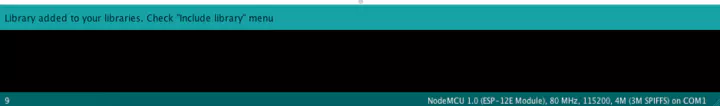
Si se carga correctamente, obtendrá la respuesta: "Biblioteca agregada a sus bibliotecas"
8. Cierre y vuelva a abrir el IDE de Arduino.
Programación del ESP8266:
Una vez configurado el ESP8266, podemos empezar a publicar y suscribir datos desde/hacia Ubidots para controlar el conmutador Wi-Fi.
1. Copia y pega el siguiente código en el IDE de Arduino. No olvides personalizar el SSID y la contraseña del Wi-Fi, así como tu Ubidots .
/**************************************** * Bibliotecas ****************************************/ #include "UbidotsESPMQTT.h" /*************************************** * Definir constantes ****************************************/ #define TOKEN "................................." // Su TOKEN de Ubidots #define WIFINAME "........." // Su SSID #define WIFIPASS "........." // Su contraseña Wifi #define DEVICE_LABEL "wifiswitch" // Nombre del dispositivo #define VARIABLE_LABEL1 "light" // Nombre de la variable Ubidots const int ERROR_VALUE = 65535; // Valor del error const uint8_t NUMBER_OF_VARIABLES = 2; // Cantidad de variables a las que el programa se va a suscribir char * variable_labels[NUMBER_OF_VARIABLES] = {"light"}; // Nombres de las variables #define luz 0 #define boton 2 int seguro=0; int ledState = LOW; // el estado actual del pin de salida int buttonState; // la lectura actual del pin de entrada int lastButtonState = HIGH; // la lectura anterior del pin de entrada int reading; unsigned long lastDebounceTime = 0; // la última vez que se conmutó el pin de salida unsigned long debounceDelay = 50; float estadoluz; // Variable a utilizar en el código float value; // Variable para almacenar datos de entrada uint8_t variable; // Para usar con el caso del conmutador Ubidots ubiClient(TOKEN); WiFiClient client; /**************************************** * Funciones auxiliares ****************************************/ void callback(char* tema, byte* carga útil, unsigned int longitud) { char* etiqueta_variable = (char *) malloc(sizeof(char) * 30); obtener_etiqueta_variable_tema(tema, etiqueta_variable); valor = btof(carga útil, longitud); establecer_estado(etiqueta_variable); ejecutar_casos(); libre(etiqueta_variable); //////////////////Luz////////////////////// digitalWrite(luz, estadoluz); ///////////////////Luz////////////////////// } // Analizar el tema para extraer la etiqueta de la variable que cambió de valor void get_variable_label_topic(char * topic, char * variable_label) { Serial.print("topic:"); Serial.println(topic); sprintf(variable_label, ""); for (int i = 0; i < NUMBER_OF_VARIABLES; i++) { char * result_lv = strstr(topic, variable_labels[i]); if (result_lv != NULL) { uint8_t len = strlen(result_lv); char result[100]; uint8_t i = 0; for (i = 0; i < len - 3; i++) { result[i] = result_lv[i]; } result[i] = '\0'; Serial.print("La etiqueta es: "); Serial.println(resultado); sprintf(variable_label, "%s", resultado); break; } } } // Convierte desde una matriz de caracteres a un valor flotante. float btof(byte * payload, unsigned int length) { char * demo = (char *) malloc(sizeof(char) * 10); for (int i = 0; i < length; i++) { demo[i] = payload[i]; } float value = atof(demo); free(demo); valor de retorno; } // Máquina de estados para usar el caso de cambio void set_state(char* variable_label) { variable = 0; for (uint8_t i = 0; i < NUMBER_OF_VARIABLES; i++) { if (strcmp(variable_label, variable_labels[i]) == 0) { break; } variable++; } if (variable >= NUMBER_OF_VARIABLES) variable = ERROR_VALUE; // No válido } // Función con switch case para determinar qué variable cambió y asignar el valor acorde a la variable de código void execute_cases() { switch (variable) { case 0: estadoluz = value; Serial.print("Luz: "); Serial.println(estadoluz); Serial.println(); break; case ERROR_VALUE: Serial.println("error"); Serial.println(); break; default: Serial.println("default"); Serial.println(); } } /*************************************** * Funcion principal ****************************************/ void setup() { // coloca aquí tu código de configuración, para ejecutar una vez: pinMode(luz, OUTPUT); pinMode(boton, INPUT); ubiClient.ubidotsSetBroker("industrial.api.ubidots.com"); // Establece el broker correctamente para la cuenta comercial ubiClient.setDebug(true); // Pasa un valor booleano verdadero o falso para activar los mensajes de depuración Serial.begin(115200); ubiClient.wifiConnection(WIFINAME, WIFIPASS); ubiClient.begin(callback); if(!ubiClient.connected()){ ubiClient.reconnect(); } char* deviceStatus = getUbidotsDevice(DEVICE_LABEL); if (strcmp(deviceStatus, "404") == 0) { ubiClient.add("light", 0); //Inserta tu variable Labels y el valor que se enviará ubiClient.ubidotsPublish(DEVICE_LABEL); ubiClient.loop(); } ubiClient.ubidotsSubscribe(DEVICE_LABEL,VARIABLE_LABEL1); //Insertar las etiquetas del dispositivo y de la variable Serial.println(variable_labels[1]); } void loop() { // Pon tu código principal aquí, para que se ejecute repetidamente: if(!ubiClient.connected()){ ubiClient.reconnect(); ubiClient.ubidotsSubscribe(DEVICE_LABEL,VARIABLE_LABEL1); //Insertar las etiquetas del dispositivo y de la variable } ubiClient.loop(); readit(); debounce(); // Guarda la lectura. La próxima vez que pases por el bucle, será lastButtonState: lastButtonState = reading; } void readit(){ // Lee el estado del interruptor en una variable local: reading = digitalRead(boton); if (reading != lastButtonState) { // Reinicia el temporizador antirrebote lastDebounceTime = millis(); } } void debounce(){ if ((millis() - lastDebounceTime) > debounceDelay) { // sea cual sea la lectura, ha estado allí durante más tiempo que el retraso del rebote, así que tómalo como el estado actual real: readit2(); } } void readit2(){ // si el estado del botón ha cambiado: if (reading != buttonState) { buttonState = reading; toggle(); } } void toggle(){ // solo alterna el LED si el nuevo estado del botón es BAJO if (buttonState == LOW) { ledState = !ledState; // establece el LED: digitalWrite(luz, ledState); ubiClient.add("light", ledState); //Inserta tu variable Labels y el valor que se enviaráubidotsPublish(DEVICE_LABEL); } } char* obtenerUbidotsDevice(char* etiquetaDeDispositivo) { char* datos = (char *) malloc(tamañode(char) * 700); char* respuesta = (char *) malloc(tamañode(char) * 400); sprintf(datos, "GET /api/v1.6/devices/%s/", etiquetaDeDispositivo); sprintf(datos, "%s HTTP/1.1\r\n", datos); sprintf(datos, "%sHost:ubidots.com\r\nUser-Agent:wifiswitch/1.0\r\n", datos); sprintf(datos, "%sX-Auth-Token: %s\r\nConexión: cerrada\r\n\r\n", datos, TOKEN); free(datos); si (cliente.conectar("ubidots.com", 80)) { cliente.println(datos); } de lo contrario { free(datos); free(respuesta); devolver "e"; } int tiempo de espera = 0; mientras (!cliente.disponible() && tiempo de espera < 5000) { tiempo de espera++; si (tiempo de espera >= 4999){ free(datos); free(respuesta); devolver "e"; } retraso(1); } int i = 0; mientras (cliente.disponible()) { respuesta[i++] = (char)cliente.leer(); si (i >= 399){ romper; } } char * pch; char * códigoDeEstado; int j = 0; pch = strtok(respuesta, " "); mientras (pch != NULL) { si (j == 1 ) { códigoDeEstado = pch; } pch = strtok (NULL, " "); j++; } free(respuesta); devolver código de estado; }
2. Subiendo el código al ESP8266:
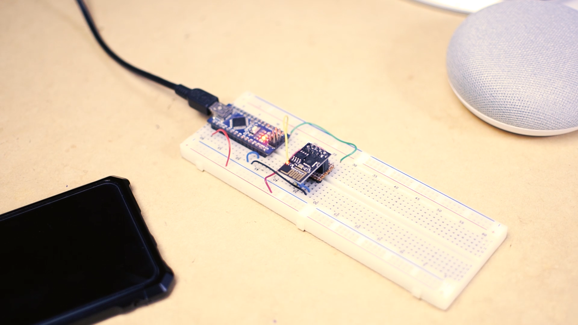
Para subir el código al ESP8266 necesitamos una interfaz serial para comunicar (Programador) el módulo con el PC, podemos utilizar conversores USB a TTL, pero en este caso vamos a utilizar el serial del Arduino que hacen muy buen trabajo.
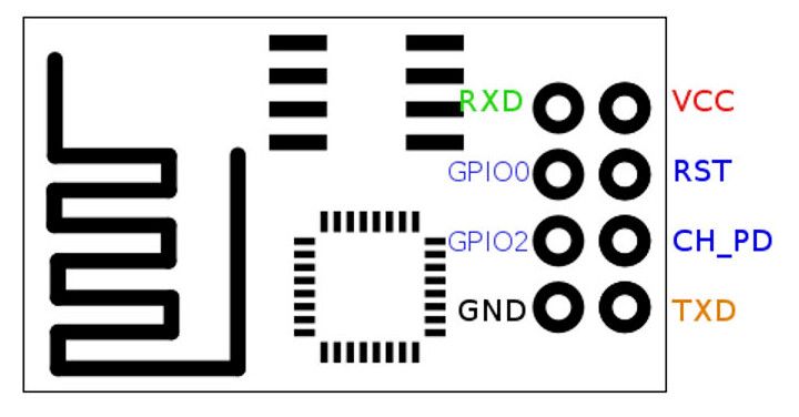
Para cargar el código en el ESP8266 debes seguir las conexiones a continuación.
| Arduino Nano | ESP8266 |
|---|---|
| TXD | TXD |
| RXD | RXD |
| 3,3 V | VCC |
| Tierra | Tierra |
| 3,3 V | CH_PD |
| Tierra | GPIO0 |
NOTA: Tenga cuidado con el VCC del ESP8266, solo funciona con una fuente de alimentación de 3,3 V.

Ahora, verifique que su código sea correcto haciendo clic en el botón de verificación en el IDE de Arduino sobre el editor.

Una vez verificado el código, recibirás una respuesta similar a la que aparece a continuación, indicando que está configurado correctamente.

A continuación, debes cargar el código en tu NodeMCU. Para ello, selecciona el icono de la flecha derecha junto al icono de verificación.

Una vez cargado el código, recibirás el siguiente mensaje en el IDE de Arduino:

5. Configura los comandos de voz con el Asistente de Google:
Para controlar tu Switch WiFi con Google Home, primero debemos configurar una plataforma intermediaria llamada IFTTT . Esta nos permitirá emparejar el Switch con el Asistente de Google. Para configurarlo correctamente, sigue los pasos a continuación.
Si no tienes una cuenta, Regístrate.
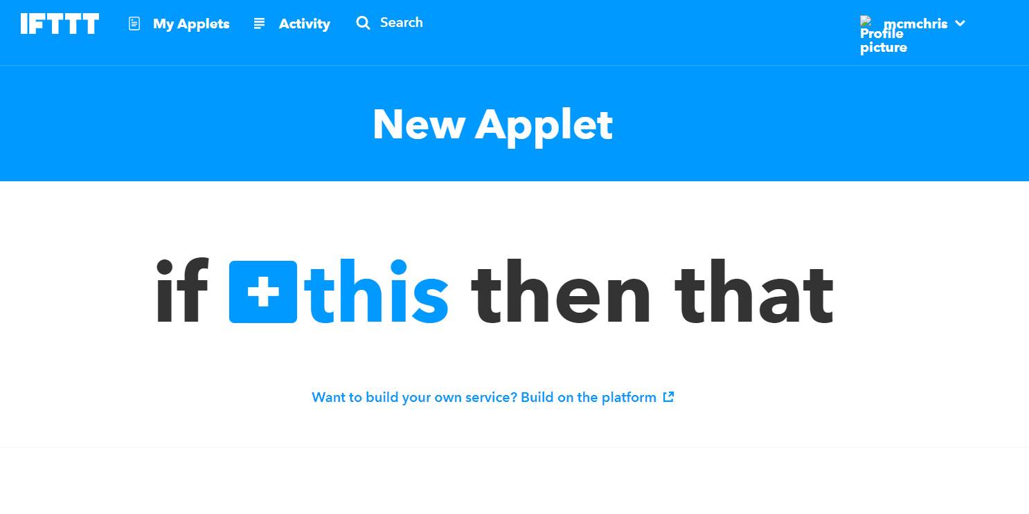
Haga clic en “Mis applets”.

Luego haga clic en “Nuevo subprograma”.
Haga clic en “ + esto ” para configurar el disparador de su condición.
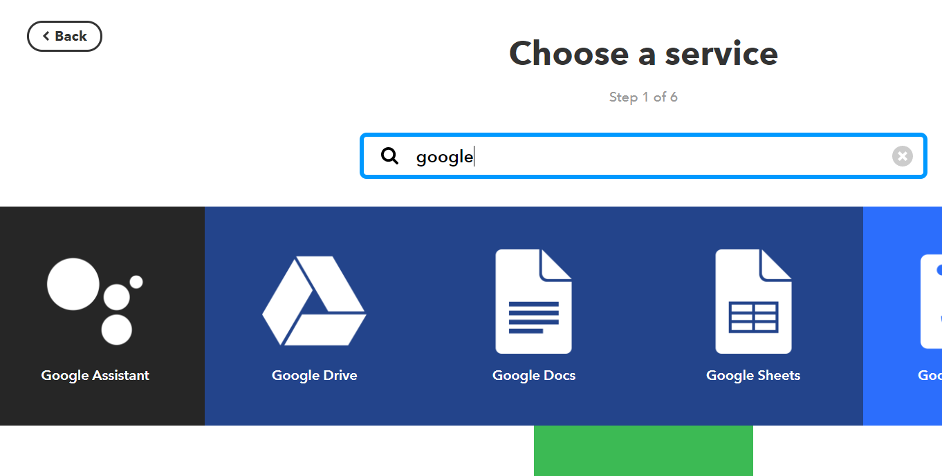
Busque el servicio “Google Assistant” y haga clic en él.
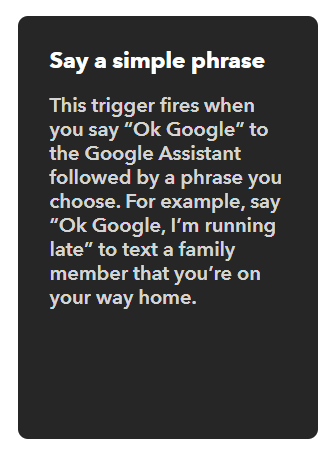
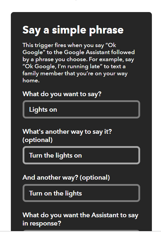
Haz clic en “Decir una frase sencilla”.
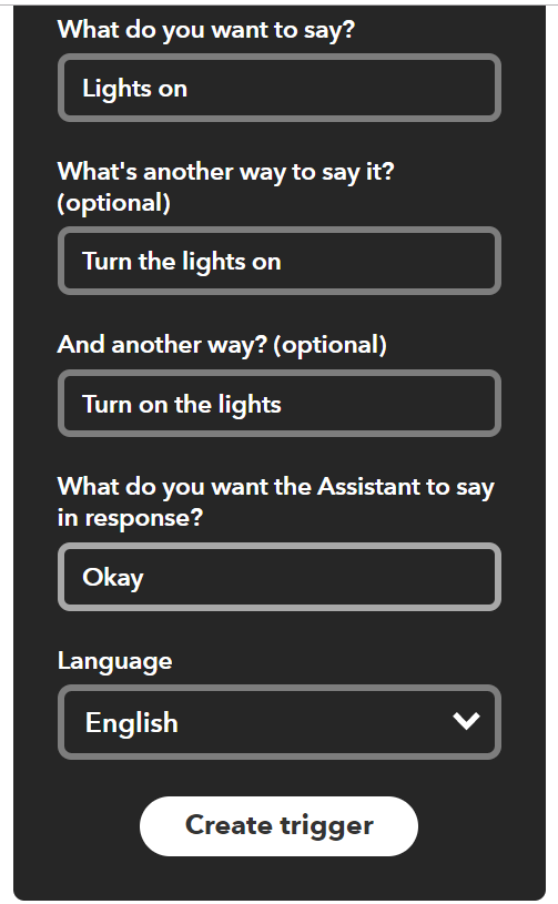
Complete los campos de activación con las frases que desea utilizar para controlar la luz, la respuesta y el idioma, luego haga clic en “ Crear activador ”.
Luego, haga clic en “ +eso ” para configurar la acción.

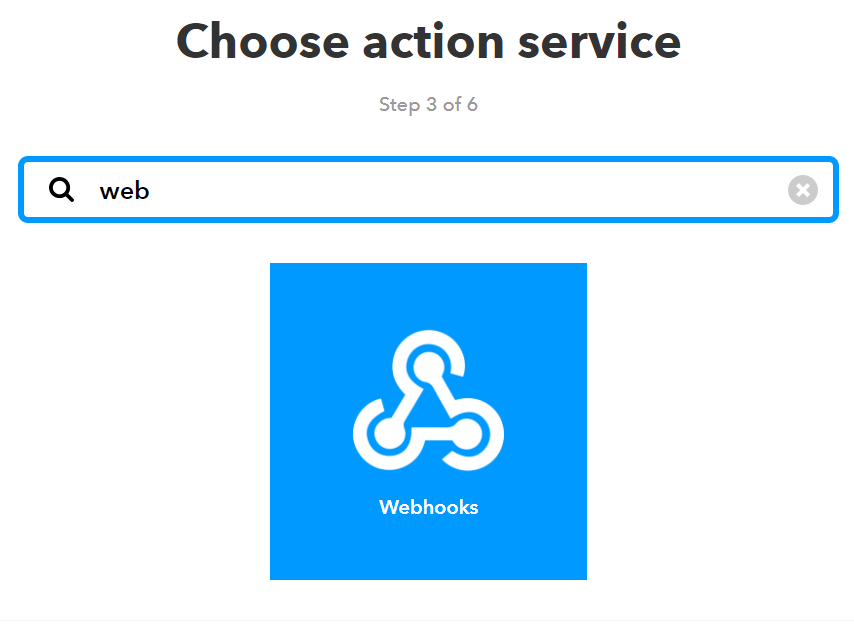
Busque el servicio de acción Webhooks
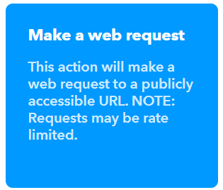
Haga clic en “ Realizar una solicitud web ”.
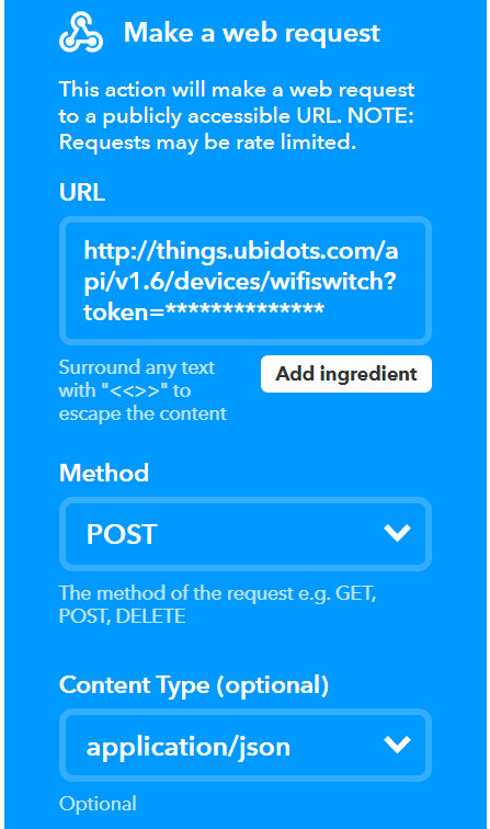
Completar campos de acción:
| Campo | Argumento |
|---|---|
| URL | http://things.ubidots.com/api/v1.6/devices/wifiswitch?token= Ubidots va tu token ubidots ) |
| Método | CORREO |
| Tipo de contenido | aplicación/json |
| Cuerpo | Para encender {“light”:1}, para apagar {“light”:0} |
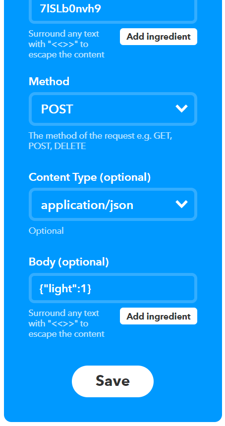
Por último, haga clic en Finalizar.

NOTA: Repita todo para configurar el subprograma “ Apagar la luz ”, con la del cuerpo .
6. Sesión de prueba:
Siguiendo el diagrama que se muestra en la imagen, conecte correctamente el módulo a su aparato de CA.
| Inicio | Módulo |
|---|---|
| Línea | L |
| Neutral | norte |
| 'Línea de luz' | B |
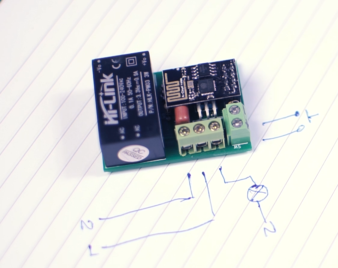
Añade un botón momentáneo de tu preferencia en el bloque terminal llamado SW.
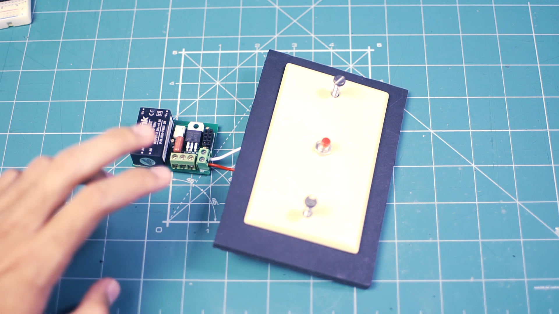
Identifique los cables de Línea, Neutro y Luz:
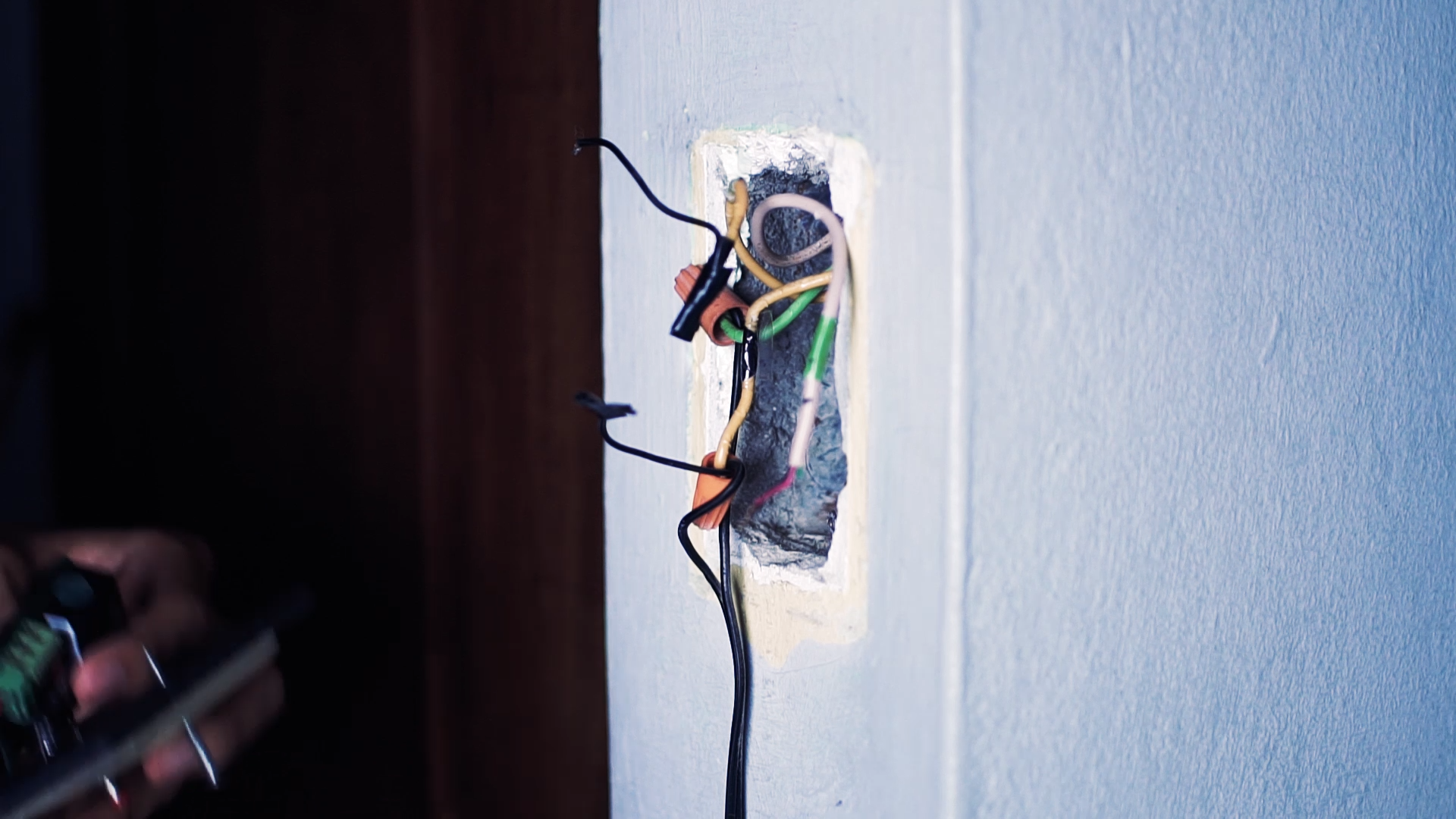
Realizar las conexiones y colocar el botón, apretar los tornillos y probar.
Si eres un aprendiz visual, consulta el siguiente videotutorial. Encontrarás todos los pasos que seguí para crear este proyecto, explicados detalladamente:
Resumen:
En esta guía, aprendimos a construir un interruptor WiFi que se puede controlar por internet con la voz, una aplicación móvil o una PC. Este interruptor permite controlar una bombilla en una habitación o cualquier otro lugar. Este dispositivo funciona con el módulo WiFi ESP8266, un pequeño módulo que facilita la conexión a internet. Además, se puede usar para controlar diversos dispositivos, como ventiladores, motores, cortinas, luces, tiras LED y mucho más.
Comience a desarrollar sus soluciones IoT con Ubidots, hoy mismo.